In this guide
Part 12: SEP Risk Management, V&V & Configuration Management
Published: January 2025 | Category: Systems Engineering
1. Introduction: Setting the Stage for Part 12
The Systems Engineering Plan (SEP) serves as the master blueprint for how a technical program will be executed. While early parts of the SEP focus on stakeholder needs, requirements definition, and architectural design, Part 12 consolidates the technical management processes that keep the program on track throughout the system life cycle. This section addresses the critical enablers of program success: risk management, verification and validation (V&V), configuration management (CM), and interface control.
Direct Answer: Part 12 translates strategic program objectives into disciplined execution mechanisms. Without robust risk management, programs encounter unforeseen threats that derail schedules and budgets. Without rigorous V&V, systems fail to meet requirements, leading to costly retrofits or field failures. Without configuration management, the engineering team loses control over evolving designs, creating integration chaos. Together, these processes form the governance backbone that ensures the system delivered matches the system designed.
This article targets systems engineers, project managers, and program-office staff who need actionable guidance for developing, executing, and continuously improving Part 12 deliverables. You will find step-by-step workflows, ready-to-use templates, real-world case studies from aerospace and defense programs, and recommendations for integrating Model-Based Systems Engineering (MBSE) tools with Part 12 activities.
2. Part 12 within the Systems Engineering Plan Structure
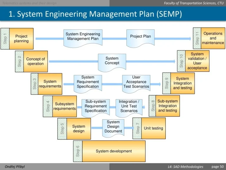
The SEP follows a standardized architecture defined in guidance such as NASA Systems Engineering Handbook (NASA-STD-7120.1 or current edition) and DoD Systems Engineering Plan guidance (per DoD 5000.02). Part 12 sits at the intersection of planning and execution, bridging the gap between upstream requirements activities (Parts 3-5) and downstream test and evaluation phases (Parts 13-14).
According to ISO/IEC/IEEE 15288, technical management processes provide the framework for monitoring, evaluating, and controlling the technical effort. Part 12 operationalizes this framework for a specific program context.
Core Deliverables of Part 12
- Risk Management Plan: Documents the risk identification, analysis, mitigation, and monitoring workflow
- Verification and Validation Plan (V-Plan): Defines how each requirement will be verified and how system validation will be demonstrated
- Configuration Management Plan: Establishes baseline control, change governance, and version management per ISO 10007 and EIA-649
- Interface Control Documents (ICDs): Captures inter-subsystem and external interfaces
- Metrics and Reporting Artifacts: Provides visibility into program health and process effectiveness
The relationship between Part 12 and other SEP sections is bidirectional. Requirements flow down from Part 4 into verification matrices. Design outputs from Part 6 become configuration items. Interface definitions inform both risk analysis and verification planning. Understanding these dependencies ensures Part 12 remains synchronized with the rest of the SEP.
| Part 12 Activity | ISO/IEC/IEEE 15288 Process | INCOSE SE Handbook Reference | NASA/DoD Guidance |
|---|---|---|---|
| Risk Management | Technical Management – Risk Management | Chapter 7 (Risk Management) | NPR 7123.1; DoD 4245.9-M |
| Verification Planning | Technical Management – Assessment | Chapter 6 (System/Subsystem Design) | NASA-STD-7009; MIL-STD-1540 |
| Configuration Management | Technical Management – Configuration Management | Chapter 5 (Program Environmental) | MIL-STD-973; EIA-649B |
| Interface Control | Technical Management – Decision Management | Chapter 4 (Requirements) | MIL-STD-1553; ICD standards |
3. Standards Alignment and Framework References
Part 12 implementation should align with established standards to ensure program compliance and industry recognition. The following references provide authoritative guidance for each technical management domain.
International Standards
- ISO/IEC/IEEE 15288:2015 — Systems and Software Engineering — System Life Cycle Processes. This standard defines the technical management processes including risk management, configuration management, and technical assessment.
- IEEE Std 15288.1-2014 — Technical Management — Assessment. Defines verification and validation assessment processes.
- IEEE Std 15288.2-2014 — Technical Management — Decision Management. Addresses interface and integration decision processes.
- ISO 10007:2017 — Quality Management — Guidelines for Configuration Management.
- ISO/IEC/IEEE 12207:2017 — Systems and Software Engineering — Software Life Cycle Processes. Relevant for software-intensive system configuration.
Industry Standards
- INCOSE Systems Engineering Handbook v4 (2015) or v5 (2020) — Provides comprehensive guidance on risk, V&V, and CM processes aligned with practice.
- SEBoK (Systems Engineering Body of Knowledge) — Available at bksebok.org, provides reference knowledge on all Part 12 topics.
- EIA-649B — Configuration Management Standard recognized across defense and aerospace industries.
- SAE EIA-649B — National Consensus Standard for Configuration Management.
Government and Regulatory Standards
- NASA NPR 7123.1 — NASA Systems Engineering Processes and Requirements.
- NASA-STD-7120.1 — NASA Systems Engineering Requirements.
- NASA-STD-7009 — Standard for Models and Simulations.
- DoD 5000.02 — Operation of the Adaptive Acquisition Framework.
- MIL-STD-881C — Work Breakdown Structures for Defense Materiel Items.
- MIL-STD-973 — Configuration Management (canceled but historically referenced).
- MIL-STD-1553 — Digital Time Division Command/Response Multiplex Data Bus.
- MIL-STD-1540 — Requirements for Launch, Space and Ground Vehicles.
- CMMI for Development — Configuration Management process area.
Domain-Specific Standards by Industry
- Aerospace: DO-178C (Software Considerations in Airborne Systems), FAA AC 20-115 (Airborne Software Certification)
- Automotive: ISO 26262 (Functional Safety), ISO/SAE 21434 (Cybersecurity)
- Medical: IEC 62304 (Software Life Cycle Processes), ISO 14971 (Risk Management)
- Rail: EN 50126 (RAMSS), EN 50128 (Software), EN 50129 (Safety)
4. Risk Management Process for Part 12
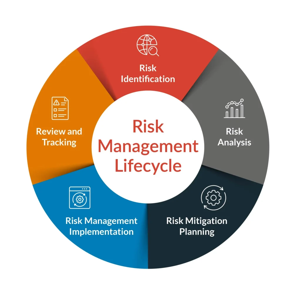
Risk management is a proactive, iterative process that anticipates threats and opportunities before they impact program objectives. Per ISO/IEC/IEEE 15288, the risk management process consists of five core activities: identification, analysis, mitigation planning, monitoring, and reporting.
Step-by-Step Risk Management Workflow
Step 1: Risk Identification
Capture risks from multiple sources: design reviews, subsystem assessments, historical program data, and stakeholder input. Each risk should be stated clearly using the format: “Because of [cause], [risk event] may occur, leading to [effect].” Per INCOSE Systems Engineering Handbook, structured risk statements improve analysis accuracy and mitigation effectiveness.
Step 2: Risk Analysis
Assess each risk against two dimensions: likelihood (probability of occurrence) and impact (severity of consequences). A probability-impact matrix helps categorize risks for prioritization. Organizations should establish their own scoring thresholds based on program risk appetite and stakeholder tolerance. The following example illustrates typical organizational approaches:
| Probability | Impact | Score Range | Category |
|---|---|---|---|
| Rare (1) | Negligible | 1-4 | Low |
| Unlikely (2) | Minor | 5-9 | Medium |
| Possible (3) | Moderate | 10-15 | High |
| Likely (4) | Major | 16-20 | Critical |
| Almost Certain (5) | Catastrophic | 25 | Extreme |
Note: Specific scoring thresholds vary by organization. Programs should define their own thresholds based on risk policy and stakeholder risk tolerance.
Step 3: Mitigation Planning
For risks scoring above a defined threshold (typically 10, though organizations may set different values), develop mitigation strategies categorized as avoidance, transfer, reduction, or acceptance. Assign risk owners responsible for implementing and tracking mitigations. Per DoD Risk, Issue, and Opportunity Management Guide, effective mitigations should have measurable success criteria.
Step 4: Monitoring and Reporting
Track risk status weekly for critical items and monthly for lower-priority risks. Update probability and impact assessments as mitigations are implemented or conditions change.
Risk Register Template
| Risk ID | Description | Category | Probability | Impact | Score | Mitigation | Owner | Status |
|---|---|---|---|---|---|---|---|---|
| R-001 | Due to supplier lead-time variability, the inertial measurement unit may be delayed, causing schedule slip | Supply Chain | 4 | 4 | 16 | Identify alternate supplier; order long-lead items early | Supply Chain Lead | Open |
| R-002 | Because of thermal expansion, the composite housing may crack during thermal cycling | Design | 3 | 4 | 12 | Perform FEA analysis; add strain relief features | Structural Engineer | In Progress |
Aerospace Case Study: Orion Program Risk Management
During the Orion Exploration Flight Test-1 (EFT-1) program, engineers identified risks related to thermal protection system (TPS) attachment under high acoustic loads. The risk scoring reached critical levels during preliminary design. Mitigation involved iterative acoustic testing at component level, design modifications to bracket geometry, and ultimately successful flight qualification. Per publicly available NASA documentation, structured risk management enabled NASA to address technical threats proactively throughout the development program, with risk registers capturing multiple risks across avionics, structures, and propulsion domains.
Note: Specific quantitative claims about risk register size should be verified against official NASA EFT-1 program documentation.
5. Verification & Validation Planning
Verification answers: “Did we build the system right?” Validation answers: “Did we build the right system?” Both processes are essential for demonstrating compliance with stakeholder expectations and regulatory requirements. Per IEEE Std 15288.2, these processes are integral to technical assessment and decision management.
Verification Methods
Per IEEE Std 15288.2, the four standard verification methods are:
- Analysis: Analytical calculations, finite element analysis, simulation. Used when physical testing is impractical or expensive.
- Inspection: Visual examination, review of design data, dimensional checks. Appropriate for verifying physical characteristics and documentation compliance.
- Demonstration: Operational exercises showing system functions without detailed measurement. Validates that functions can be performed as specified.
- Test: Formal testing with measured criteria, environmental exposure, performance characterization. Provides objective evidence of compliance.
Building a Verification Matrix
The verification matrix maps each requirement to a verification method, acceptance criteria, environment, and responsible party. This traceability matrix is a critical deliverable per ISO/IEC/IEEE 15288 and industry practice. Follow these steps:
- Extract all requirements from Part 4 of the SEP
- Assign an appropriate verification method based on requirement type (performance, interface, environmental)
- Define measurable acceptance criteria for each verification activity
- Identify test articles, facilities, and resources needed
- Schedule verification activities aligned with program milestones
Verification Matrix Example
| Req ID | Requirement Text | Verification Method | Acceptance Criteria | Environment | Evidence |
|---|---|---|---|---|---|
| REQ-001 | System shall survive 15g shock loading without damage | Test | No structural failure; functional verification post-shock | Shock test facility | Test report, post-test inspection |
| REQ-002 | Software shall process sensor data within 50ms | Test | 95% of samples within 50ms latency | Integration lab | Latency log, analysis report |
| REQ-003 | Mechanical interface shall conform to applicable interface specifications | Inspection | Drawing dimensions within tolerance | Manufacturing | First Article Inspection report |
Validation Approach
Validation focuses on meeting stakeholder needs rather than just satisfying allocated requirements. Per INCOSE Systems Engineering Handbook, validation answers whether the right system was built by demonstrating operational capability in its intended environment. Validation activities include operational demonstrations, user acceptance testing, and end-to-end scenario execution. The V-Plan should identify validation objectives, success metrics, and environments (lab, simulation, or operational) for each validation event.
6. Configuration Management and Change Control
Configuration management ensures that the product baselines are defined, documented, and controlled throughout the life cycle. Per ISO 10007 and EIA-649B, without rigorous CM, engineering changes proliferate without coordination, leading to integration failures and traceability gaps.
Configuration Item Selection
Identify configuration items (CIs) based on their significance to the system. Typical CIs include:
- End items delivered to the customer
- Software baselines
- Critical assemblies and components affecting form, fit, or function
- Support equipment and tooling
- Documentation (drawings, specifications, manuals)
Baseline Establishment
Three baselines define configuration control per ISO/IEC/IEEE 15288 and industry practice:
- Functional Baseline: Allocated requirements and top-level architecture. Established after preliminary design review (milestone timing varies by program and standard).
- Allocated Baseline: Derived requirements and interface definitions. Established after critical design review (milestone timing varies by program and standard).
- Product Baseline: Design documentation defining the as-built product. Established after initial operational capability or equivalent milestone (timing varies by program).
Note: Baseline milestone alignment varies by program and regulatory framework. Programs should define baseline timing in their CM plan per applicable guidance.
Change Control Board (CCB) Process
All changes to controlled baselines flow through a Change Control Board per MIL-STD-973 (historical reference) and EIA-649B. The CCB evaluates changes based on technical impact, schedule impact, cost impact, and risk. Approved changes are assigned an engineering change proposal (ECP) number and incorporated through a controlled revision process.
Configuration Management Plan Template
A CMP tailored for Part 12 should include:
- CM Objectives: Ensure configuration visibility and control across program phases
- Configuration Items: List of all CIs with unique identifiers and responsible engineers
- Baseline Definition: Description of functional, allocated, and product baselines with approval authority
- Change Control Process: CCB composition, authority levels, and change categories (minor vs. major)
- Version Control: Naming conventions, revision numbering, and release procedures
- Documentation Control: Drawing standards, specification control, and record retention
- Tools and Repositories: PLM system (such as Teamcenter, Windchill, or equivalent), document control system, and model repository locations
7. Interface Management & Integration
Interface control documents formalize the physical, electrical, logical, and procedural boundaries between subsystems. Per INCOSE Systems Engineering Handbook, poor interface management is a leading cause of integration failures and schedule delays.
Creating Interface Control Documents
ICDs should capture:
- Interface Identification: Unique ICD