Systems Engineering Plan — Part 19: A Practical Guide to Risk, Safety, and Compliance
Direct Answer: Part 19 of a Systems Engineering Plan is the dedicated section that integrates risk management, safety analysis, and reliability planning into a coherent framework ensuring systems meet performance goals while maintaining regulatory compliance throughout the lifecycle. This section establishes the workflows, deliverables, and metrics that keep a program on track, connecting technical decision-making to program risk posture.
Introduction
A Systems Engineering Plan defines how engineering activities will be conducted across a program’s lifecycle. Part 19 of the Systems Engineering Plan occupies a unique position: it bridges technical execution with program health by systematically identifying hazards, quantifying risks, and ensuring that safety and reliability requirements are woven into every engineering decision.
For engineers, program managers, and stakeholders, Part 19 is not merely a compliance checkbox. It is a practical tool that guides teams through early risk identification, ongoing hazard analysis, and continuous safety monitoring. When executed effectively, Part 19 prevents costly redesigns, reduces schedule slippage, and demonstrates to customers and regulators that the system has been developed with rigor and accountability.
This guide explains the scope of Part 19, maps it to relevant standards, clarifies its dependencies on other SEP sections, and provides actionable workflows, templates, and best practices. For related guidance, see the requirements management section (Part 2) and the design integration section (Part 4).
1. What is Part 19? – Scope and Core Objectives
Part 19 of a Systems Engineering Plan typically encompasses four interconnected domains:
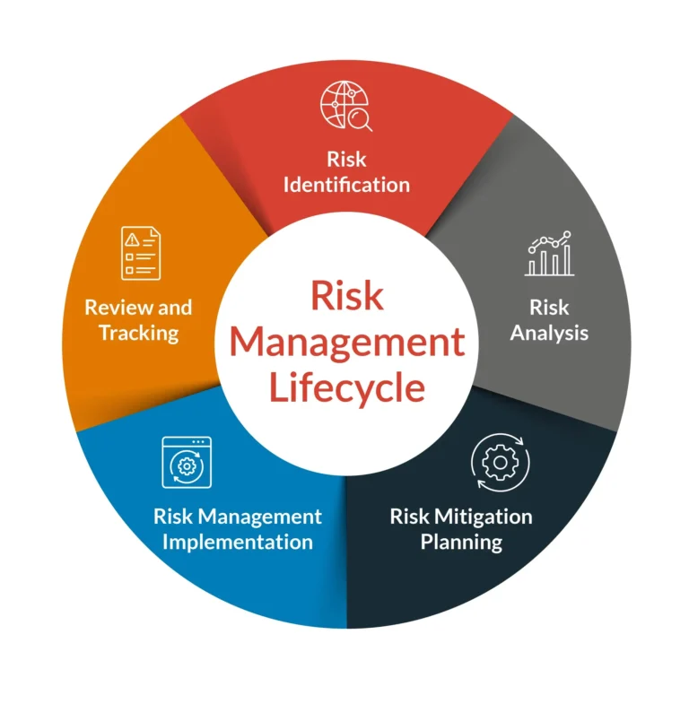
- Risk Identification and Mitigation Planning: Systematic discovery of technical, programmatic, and external risks that could affect system performance, cost, or schedule. Mitigation strategies are developed and tracked throughout the program.
- Safety and Hazard Analysis: Identification of hazards that could cause harm to users, the environment, or assets. Analysis methods include Preliminary Hazard Analysis (PHA), Failure Modes and Effects Analysis (FMEA), Fault Tree Analysis (FTA), and System-Theoretic Process Analysis (STPA).
- Reliability and Maintainability Planning: Definition of reliability targets using metrics such as Mean Time Between Failures (MTBF), Failure In Time (FIT) rates, and probability of failure on demand. Includes maintainability requirements and plans for demonstrating system availability over its operational life.
- Integrated Risk-Safety Workflow: The thread connecting risk and safety activities to requirements management, design decisions, verification activities, and configuration management so that risk data remains current and actionable.
Quick-Start Checklist
- Establish a centralized risk register linked to system architecture
- Conduct Preliminary Hazard Analysis during concept phase
- Define reliability targets and prediction methodologies
- Map deliverables to applicable standards requirements
- Integrate risk review into design review gate criteria
- Assign risk owners with defined escalation thresholds
- Maintain bidirectional traceability between risks, hazards, and requirements
2. Standards Landscape – Aligning Part 19 with Applicable Requirements
Part 19 does not exist in isolation. It must align with established engineering standards that define expectations for risk and safety across different industries. Understanding these alignments helps tailor Part 19 activities to satisfy both contractual and regulatory requirements.
| Standard |
Risk Management Requirements |
Safety Analysis Requirements |
Domain |
ISO/IEC/IEEE 15288:2023
Clause 6.4.3 (Risk Management) |
Systematic risk identification, analysis, treatment, and monitoring |
Links to validation and operational readiness |
Cross-domain |
INCOSE Systems Engineering Handbook v4
Chapter 4 (Technical Management) |
Integrated risk management throughout lifecycle |
Hazard analysis integration with SE processes |
Cross-domain |
NASA Systems Engineering Handbook
NASA-SP-2016-3402 |
Formal risk management process per NPR 8000.4 |
Detailed hazard analysis and safety assessment |
Space, aerospace |
| MIL-STD-882E (System Safety) |
Risk assessment matrix methodology |
Mandatory system safety program per MIL-STD-882E |
Defense |
SAE ARP 4754A
Section 5 (Safety Assessment) |
Development assurance risk assessment |
Particular Risk Analysis (PRA), Functional Hazard Assessment (FHA) |
Civil aviation |
| ECSS-E-ST-10-02C |
Risk management per ECSS-M-ST-10C |
System safety assessment including PHA, SHA, FMEA, FTA |
European space |
| ISO 26262 |
Automotive safety lifecycle risk management |
Item definition, hazard analysis, automotive FMEA |
Automotive |
Important Standards Notes:
- IEEE Std 1220 was withdrawn and its content incorporated into IEEE Std 15288; programs should reference ISO/IEC/IEEE 15288:2023 for current requirements.
- MIL-STD-499 was cancelled in 2014; current DoD programs typically reference MIL-STD-882E for system safety and MIL-STD-1388-1A for logistics.
- DoD 5000.02 (currently DoDI 5000.02, “Operation of the Adaptive Acquisition Framework”) governs defense acquisition and references current risk management requirements.
- INCOSE Systems Engineering Handbook v4 (2020) is widely referenced; verify program requirements for v5 (2024) applicability.
3. Relationship to Other SEP Sections
Part 19 functions as an integrative thread rather than a standalone module. Its effectiveness depends on tight coupling with other SEP sections:
Requirements Management (Part 2): Risk and safety requirements derived from Part 19 must flow into the requirements database. Changes to risk posture may trigger requirement modifications, and requirement volatility should feed back into risk registers. See Part 2: Requirements Management for integration guidance.
Design (Part 4): Design decisions must consider identified hazards and reliability constraints. The design team should review hazard logs before finalizing architectural choices, and risk reduction strategies may drive design margin requirements. See Part 4: Design.
Verification and Validation (Part 7): Verification criteria for safety-critical functions must be traceable to hazard mitigations. Validation activities should confirm that the system operates safely under realistic conditions. See Part 7: Verification and Validation.
Configuration Management (Part 9): Risk registers, hazard logs, and safety cases are configuration items. Change control processes must evaluate the impact of proposed changes on risk and safety status. See Part 9: Configuration Management.
Integration and Test (Part 12): Test plans should include scenarios that exercise identified risks and verify that mitigations are effective. Integration events provide opportunities to validate safety-related behaviors. See Part 12: Integration and Test.
4. Expected Deliverables and Documentation
Part 19 generates a set of formal artifacts that document your risk and safety posture. The specific list varies by program, but the following are commonly required:
Risk Register: A structured repository of identified risks, their likelihood and consequence ratings, assigned owners, mitigation strategies, and status. The Risk Priority Number (RPN) can be calculated as Likelihood × Severity × Detectability for prioritized handling.
Hazard Log: A comprehensive list of hazards, their associated causes and effects, severity and probability ratings, and controls or mitigations. The hazard log serves as the primary input to safety case development.
Safety Case: A structured argument, supported by evidence, demonstrating that the system achieves acceptable risk levels for identified hazards. Safety cases typically follow the ALARP (As Low As Reasonably Practicable) framework for demonstrating risk acceptability.
Reliability/Maintainability Plan: Defines reliability targets using metrics such as MTBF, availability (A), and unavailability (Q), along with prediction methodologies, maintainability metrics, and demonstration strategies.
Data Management Plan: Specifies how risk and safety data will be captured, stored, versioned, and accessible throughout the program. Integration with Model-Based Systems Engineering environments is increasingly expected.
5. Step-by-Step Implementation Workflow
Implementing Part 19 effectively requires a phased approach integrated with the broader SEP schedule:
Phase 1: Early Risk Identification (Concept Phase)
Begin risk identification during concept exploration. Conduct initial hazard analyses using PHA or STPA, capture top-level risks, and establish preliminary reliability targets. Define the risk management approach that will govern subsequent phases.
Phase 2: Detailed Risk and Safety Analysis (Development Phase)
As the system architecture matures, perform detailed analyses including FMEA, FMECA (Failure Mode, Effects, and Criticality Analysis), FTA with minimal cut set analysis, and HAZOP for process safety. Update the risk register with refined likelihood and consequence estimates. Develop mitigation plans for high-priority risks and integrate these into design requirements.
Phase 3: Mitigation Implementation and Verification (Integration and Test Phase)
Execute planned mitigations during design and manufacturing. Conduct tests that verify mitigation effectiveness. Update the hazard log with verification evidence and revise the safety case accordingly. Perform Model-Based Safety Analysis (MBSA) where appropriate.
Phase 4: Continuous Monitoring and Maintenance (Operation Phase)
Track emerging risks, monitor risk indicator metrics, and conduct periodic risk reviews. Capture operational feedback to refine reliability predictions using actual field data and update safety documentation for future systems or derivatives.
6. Hazard Analysis Method Selection
Selecting appropriate hazard analysis methods depends on system complexity, lifecycle phase, and domain requirements. The following decision guidance supports methodology selection:
| Method |
Best For |
Lifecycle Phase |
Complexity |
| PHA (Preliminary Hazard Analysis) |
Early hazard identification, concept screening |
Concept, early development |
Any |
| FMEA/FMECA |
Component failure modes, failure propagation |
Detailed design, test planning |
Medium to high |
| FTA (Fault Tree Analysis) |
Top-event analysis, cut set identification |
Detailed design, verification |
Medium to high |
| STPA (System-Theoretic Process Analysis) |
Complex sociotechnical systems, control loop hazards |
Concept through operations |
High |
| HAZOP (Hazard and Operability Study) |
Process safety, procedure deviations |
Detailed design, operations |
Process-focused |
| Bow-Tie Analysis |
Barrier-based risk assessment, threat control |
Concept through operations |
Any |
| Monte Carlo / Sensitivity Analysis |
Quantitative risk analysis, uncertainty quantification |
Detailed design, operations |
High |
7. Best Practices for Effective Risk and Safety Management
Implementing Part 19 is not just about producing documents; it is about building a culture of proactive risk awareness. The following practices enhance effectiveness:
Use SysML for Traceability: Systems Modeling Language provides standard notation for representing risk relationships, hazard allocations, and reliability requirements within the system model. This approach keeps risk data integrated with design artifacts rather than stored in disconnected spreadsheets.
Employ Quantitative Reliability Metrics: Where appropriate, use metrics such as Mean Time Between Failures (MTBF), Mean Time To Failure (MTTF), probability of failure on demand (PFD), and availability calculations. Quantitative targets provide objective criteria for accepting or rejecting design alternatives.
Conduct Cross-Functional Risk Boards: Regular risk board meetings that include engineering, safety, program management, and customer representatives ensure that risk information informs decision-making at all levels. These forums also promote accountability for mitigation execution.
Leverage Model-Based Systems Engineering (MBSE): MBSE environments allow you to maintain live risk data linked to system architecture. When the design changes, impact analysis can automatically identify affected hazards and risks, reducing the manual effort required to keep documentation current.
Establish Clear Escalation Paths: Define thresholds that trigger elevated review or leadership awareness. A risk that exceeds a consequence threshold should automatically escalate, ensuring that appropriate resources are brought to bear before the risk materializes.
Integrate Human Factors Engineering: Consider ergonomic factors and human performance limitations in safety analysis, particularly for systems with significant operator interaction. Human error should be addressed in FMEA and fault tree development.
Address Cybersecurity Risk: For systems with networked components, integrate cybersecurity risk assessment per NIST SP 800-37 or ISO/IEC 27001 frameworks, addressing both safety and security interdependencies.
8. Common Pitfalls and How to Avoid Them
Even well-intentioned programs encounter recurring challenges with Part 19 execution. Anticipating these pitfalls helps design more robust processes:
Siloed Risk Registers: When risk registers are maintained independently by different teams without synchronization, the program loses visibility of cross-functional risks. Avoid this by establishing a single, shared risk repository with defined update responsibilities.
Under-Estimated Safety Analyses: Insufficient analysis depth leads to missed hazards and inadequate mitigations. Ensure that safety analysis scope matches system complexity and that analysts have appropriate training and tools.
Inadequate Change Control: Changes to the system design or environment can invalidate previous risk assessments. Strengthen your change control process to require risk review whenever proposed changes affect safety-related functions.
Static Documentation: Documents that are written once and never updated lose their value. Implement trigger-based review processes that prompt risk register and hazard log updates at defined milestones or events.
Disconnect Between Risk and Design: If risk data does not influence design decisions, mitigations may be overlooked or improperly implemented. Require formal design reviews to include risk and safety assessment as agenda items with documented outcomes.
Insufficient Root Cause Analysis: When failures occur, ensure Root Cause Analysis (RCA) methodologies such as TapRoot, Apollo RCA, or Ishikawa diagrams are applied to prevent recurrence.
9. Tailoring Part 19 for Diverse Program Constraints
Not all programs require the same depth of Part 19 activities. Tailoring ensures that risk management effort matches program scale and constraints:
Small-Scale Commercial Projects: Streamline documentation to focus on critical hazards and primary risks. Use templates that combine risk and safety information into a single artifact. Conduct regular but informal reviews rather than elaborate board meetings.
Large-Scale Defense Programs: These programs typically require compliance with MIL-STD-882E for system safety and applicable DoDI 5000.02 requirements, demanding comprehensive risk registers, detailed hazard logs, and formal safety cases. Allocate dedicated risk management personnel and integrate with program Earned Value Management systems. DoDAF architecture frameworks may be required for comprehensive system views.
Highly Regulated Domains (Civil Aviation, Space): Standards such as SAE ARP 4754A (with FAA Advisory Circulars and EASA Certification Specifications for aviation) and ECSS-E-ST-10 (for European space programs per NASA-STD-8739.x for U.S. space safety) mandate specific analysis methods and documentation structures. Plan additional review cycles with regulatory authorities and build in schedule margin for compliance verification activities.
Regardless of scale, maintain the core principles: identify risks early, maintain traceability, verify mitigations, and keep stakeholders informed. Tailoring reduces unnecessary effort without sacrificing program protection.
10. Metrics, Review Criteria, and Continuous Improvement
Measuring the effectiveness of Part 19 activities demonstrates program health and drives continuous improvement:
Key Performance Indicators (KPIs):
- Risk Reduction Rate: Percentage of identified risks that have been mitigated or retired within a defined period.
- Safety Coverage: Proportion of hazards that have documented controls and verified mitigations.
- Reliability Growth: Trend in reliability metrics (such as MTBF) as the system matures through testing and operation.
- On-Time Risk Review Completion: Adherence to scheduled risk review milestones.
- Risk Exposure Trend: Aggregate risk score movement over time, indicating whether program risk posture is improving or deteriorating.
Peer Reviews and Milestone Audits: Independent reviewers assess whether Part 19 deliverables meet quality standards and program expectations. Audit findings should feed into corrective action processes and lessons-learned repositories.
Lessons-Learned Sessions: At program closure or major milestones, capture insights about what worked well and what could be improved in risk and safety management. Feed these lessons back into process improvement initiatives and future program planning.
Practical resources accelerate Part 19 implementation. The following tools support integrated risk and safety management:
- Requirements Management: IBM Rational DOORS 9.7+ or JAMA Connect provide traceability between requirements, risks, and test cases.
- MBSE Environments: Cameo Systems Modeler v19.0+ or similar tools supporting SysML/UML enable integrated modeling of system architecture and risk relationships using the ARCADIA method.
- Specialized Risk Management: Resolver Risk Management Platform or similar tools provide structured workflows for risk identification, assessment, and tracking.
- Reliability Analysis: Reliability-centered tools supporting reliability prediction (e.g., MIL-HDBK-217F or Telcordia SR-332 methodologies), FMEA, and fault tree analysis.
12. Glossary of Key Terms
- ALARP
- As Low As Reasonably Practicable – a risk acceptance framework requiring that risk be reduced unless the cost of further reduction is grossly disproportionate to the benefit.
- FMEA
- Failure Modes and Effects Analysis – a systematic method for identifying potential failure modes and their effects on system behavior.
- FTA
- Fault Tree Analysis – a top-down deductive method for analyzing system failures through Boolean logic representations.
- FIT Rate
- Failure In Time – a unit expressing the number of failures per billion hours of operation.
- MTBF
- Mean Time Between Failures – the average time between failures for a repairable system.
- RPN
- Risk Priority Number – calculated as Likelihood × Severity × Detectability to prioritize risk response actions.
- STPA
- System-Theoretic Process Analysis – a hazard analysis methodology based on systems theory that addresses control loop failures.
Frequently Asked Questions
What is the scope of Part 19 in a Systems Engineering Plan?
Part 19 covers risk identification and mitigation planning, safety and hazard analysis, reliability and maintainability planning, and integrated workflows connecting these activities with other SEP sections from concept through disposal.
How does Part 19 relate to other SEP sections?
Part 19 is interdependent with Parts 2, 4, 7, 9, and 12. Risk and safety requirements flow into requirements management, design decisions must consider hazards, verification confirms mitigation effectiveness, and configuration management maintains current risk documentation.
Which standards provide guidance for Part 19?
Key standards include ISO/IEC/IEEE 15288:2023, INCOSE SE Handbook v4, NASA SE Handbook, MIL-STD-882E, SAE ARP 4754A, and ECSS-E-ST-10. Applicable standards depend on program domain and contractual requirements.
What deliverables are expected for Part 19?
Common deliverables include risk register, hazard log, safety case, reliability/maintainability plan, and data management plan. Specific requirements vary by program and applicable standards.
What challenges occur when implementing Part 19?
Frequent challenges include siloed risk registers, insufficient safety analysis depth, inadequate change control, stale documentation, and disconnect between risk data and design decisions.
How can Part 19 be tailored for specific programs?
Tailor by scaling documentation depth, review frequency, and tool usage to match program size and complexity while maintaining core principles of early risk identification, traceability, and verification.
What metrics assess Part 19 effectiveness?
KPIs include risk reduction rate, safety coverage percentage, reliability growth trends, and on-time review completion. Peer reviews and lessons-learned sessions complement quantitative metrics.
Conclusion
Part 19 of a Systems Engineering Plan is the strategic hub where risk management, safety analysis, and reliability planning intersect. When implemented effectively, it protects program outcomes by ensuring that hazards are identified early, mitigations are verified, and risk information informs every engineering decision.
The value of Part 19 extends beyond compliance. It creates a structured environment where teams can anticipate challenges, allocate resources efficiently, and demonstrate to customers and regulators that the system has been developed with rigorous attention to safety and reliability.
To succeed, integrate Part 19 activities with other SEP sections, maintain live traceability between risks, requirements, and design artifacts, and measure effectiveness through defined KPIs and regular reviews. Adopt the best practices, templates, and tools outlined in this guide to build a risk and safety culture that supports program success across defense, aerospace, and commercial domains.
Ready to strengthen your Systems Engineering Plan? Start by assessing your current Part 19 practices against this framework, identify gaps, and develop an improvement plan aligned with your program constraints and applicable standards. The investment in robust risk and safety management pays dividends throughout the system lifecycle.
For additional guidance on Systems Engineering Plan development, explore our related articles on requirements management, design integration, and verification and validation.
What is the scope of Part 19 in a Systems Engineering Plan?
Part 19 covers risk identification and mitigation planning, safety and hazard analysis, reliability and maintainability planning, and integrated workflows from concept through disposal.
Which standards apply to Part 19 activities?
ISO/IEC/IEEE 15288:2023, INCOSE SE Handbook v4, NASA SE Handbook, MIL-STD-882E, SAE ARP 4754A, and ECSS-E-ST-10 provide relevant guidance depending on program domain.