In this guide
Systems Engineering Plan: Common Mistakes and How to Avoid Them
A robust Systems Engineering Plan serves as the backbone of any complex engineering program. When executed well, it aligns stakeholders, clarifies requirements, and establishes a clear roadmap from concept through disposal. When executed poorly, it becomes a source of schedule delays, cost overruns, and compliance failures that ripple through every phase of the system lifecycle. This guide identifies the most frequent pitfalls practitioners encounter when developing their Systems Engineering Plan, explains why they occur, and provides actionable mitigation tactics grounded in ISO/IEC/IEEE 15288 and INCOSE best practices. Whether you are a systems engineer drafting your first SEP or a program manager auditing an existing plan, you will find diagnostic checklists, tool recommendations, and performance metrics designed to transform your SEP from a contractual document into a true program asset.
1. What Is a Systems Engineering Plan (SEP)?
The Systems Engineering Plan is the master planning document that defines how systems engineering activities will be performed on a specific program or project. It captures the technical approach, organizational responsibilities, milestone schedule, resource requirements, and verification strategy necessary to transform stakeholder needs into a deployable system solution. The SEP operates as both a communication artifact and a governance tool, providing stakeholders with visibility into engineering processes while establishing the baseline against which technical performance will be measured.
Core components of a comprehensive Systems Engineering Plan include:
- Requirements Management: How stakeholder needs are captured, analyzed, allocated, and traced throughout the lifecycle.
- Architecture Definition: The logical and physical decomposition of the system into components, interfaces, and behaviors.
- Verification and Validation: Methods for proving the system meets specified requirements and fulfills stakeholder expectations.
- Risk and Opportunity Management: Processes for identifying, assessing, mitigating, and monitoring technical and programmatic risks.
- Configuration Management: Controls for maintaining system integrity and traceability across baselines.
- Stakeholder Engagement: Strategies for communication, review, and consensus-building throughout the program.
- Integration Planning: Approaches for combining subsystems and managing interface conflicts.
These components align directly with the system lifecycle processes defined in ISO/IEC/IEEE 15288, which organizes systems engineering into agreement, organizational project-enabling, technical management, and technical processes. The Systems Engineering Body of Knowledge (SEBoK) provides comprehensive reference material for these processes. INCOSE’s Systems Engineering Handbook further elaborates these processes with practical guidance on execution and tailoring for different program contexts.

2. The High Cost of SEP Mistakes: Impact on Schedule, Cost, and Performance
Mistakes embedded in the Systems Engineering Plan do not remain dormant—they propagate through the program lifecycle, often with compounding effects. When requirements are unclear, downstream design activities proceed on faulty assumptions, leading to rework cycles that consume schedule margin and budget reserves. When traceability is absent, integration testing reveals conflicts that require fundamental redesign, pushing delivery dates beyond contractual obligations.
The consequences of SEP deficiencies manifest across three dimensions:
Schedule Impacts: Programs experiencing significant requirements changes after preliminary design review often encounter substantial schedule extensions. Industry studies, including research documented in the Standish Group CHAOS Report and NASA Systems Engineering Manual, indicate that late-stage requirements changes frequently result in schedule delays that can significantly impact program milestones.
Cost Overruns: Rework driven by SEP deficiencies can account for a notable portion of cost growth in complex programs. When design changes cascade through multiple subsystems, the cost multiplier effect can transform a single requirement clarification into a significant financial impact.
Performance Failures: Systems that reach operational testing with inadequate verification evidence face delays in fielding or, worse, fielding with known deficiencies that require post-deployment modification. In defense and aerospace contexts, such failures can have safety implications extending beyond programmatic concerns. Standards such as SAE ARP4754A for aerospace systems and ISO 26262 for automotive applications establish rigorous requirements for verification evidence.
Programs in the defense sector, aerospace development, and automotive industries consistently report that the root causes of major program disruptions trace back to SEP weaknesses—specifically in requirements definition, traceability, and integration planning. These patterns persist across organizational boundaries, suggesting systemic rather than isolated challenges.
3. Overview of the Most Common Systems Engineering Plan Mistakes
Analysis of program performance data and practitioner experience reveals recurring patterns in how Systems Engineering Plans fall short. These mistakes cluster into categories that, while distinct in symptom, often share common root causes related to inadequate planning, insufficient stakeholder engagement, or overconfidence in initial estimates. The ten most frequently observed SEP mistakes include:
Documentation and Requirements Issues
- Incomplete or Ambiguous Requirements: Stakeholder needs are captured incompletely or expressed in terms that permit conflicting interpretations.
- Lack of Requirements Traceability: Links between stakeholder needs, system requirements, design elements, and verification artifacts are absent or inconsistent.
- Vague Success Criteria and Metrics: The plan defines what needs to be built but does not specify how success will be measured.
Planning and Estimation Issues
- Unrealistic Schedules and Resource Estimates: Program timelines do not reflect actual engineering effort, leading to chronic schedule pressure.
- Under-estimating Integration Effort: The complexity of combining subsystems and managing interfaces is not adequately addressed in planning or scheduling.
Engagement and Governance Issues
- Insufficient Stakeholder Engagement: Key stakeholders are not consulted during requirements development, resulting in solutions that fail to meet actual needs.
- Inadequate Risk and Opportunity Management: Risks are identified superficially or mitigation strategies are not actionable.
- Non-Compliance with Industry Standards: The SEP does not align with relevant standards, creating compliance gaps and audit findings.
- Weak Configuration Management: Version control, baseline management, and change control processes are not defined clearly.
Methodology and Approach Issues
- Over-Reliance on Documentation over Model-Based Approaches: The plan emphasizes document production over model-based systems engineering, creating bottlenecks in complex system coordination.
Each of these mistakes warrants dedicated attention. The following sections examine each pitfall in depth, explaining the mechanism of failure, typical impacts, and proven mitigation tactics.
4. Mistake #1 – Incomplete or Ambiguous Requirements
Requirements form the foundation upon which all subsequent engineering activities rest. When this foundation contains gaps or ambiguities, the entire structure becomes unstable. Incomplete requirements manifest as missing functional capabilities, undefined performance boundaries, or unstated constraints that only surface during design or integration. Ambiguous requirements introduce interpretive latitude that different stakeholders may exercise in conflicting directions.
Why This Happens
Pressure to accelerate program initiation often leads teams to accept preliminary requirements before stakeholders have fully articulated their needs. Additionally, requirements elicitation techniques may be inadequate for capturing the complexity of stakeholder expectations. Cultural factors can also play a role—stakeholders may assume certain requirements are obvious, while engineers may hesitate to question ambiguous statements from customers.
Downstream Impact
Incomplete requirements cause design teams to make assumptions that may not align with stakeholder intent. These assumptions become embedded in the architecture, and correcting them later requires costly redesign. Ambiguous requirements lead to disputes during acceptance testing, as different parties interpret acceptance criteria differently. Both conditions result in rework, schedule slippage, and cost growth.
Mitigation Tactics
- Structured Elicitation Workshops: Facilitate sessions with stakeholders using techniques such as context-free questions, scenario-based exploration, and prototype demonstration to expose unstated requirements.
- Requirements Attributes: Assign each requirement attributes including source, priority, stability, and verification method to improve clarity and traceability.
- Peer Review and Ambiguity Analysis: Have requirements reviewed by personnel not involved in original authoring to identify gaps and unclear phrasing.
- Bidirectional Traceability: Link requirements to stakeholder needs and design artifacts to verify complete coverage of stakeholder intent.
Quick Checklist for Requirements Completeness
- Has each stakeholder need been mapped to at least one system requirement?
- Are all functional requirements expressed as user-visible behaviors or capabilities?
- Are performance requirements quantified with measurable thresholds?
- Are constraints explicitly stated rather than assumed?
- Has ambiguous language been eliminated through peer review?
- Are verification methods assigned to every requirement?

5. Mistake #2 – Lack of Requirements Traceability
Traceability connects the dots between what stakeholders need, what the system must do, how it will be designed, and how it will be verified. Without traceability, programs lose visibility into the impact of changes, the completeness of verification, and the alignment between design decisions and stakeholder expectations. The absence of traceability creates a fragile engineering environment where changes cascade unpredictably and compliance evidence becomes difficult to assemble.
How Missing Links Cause Integration Failures
When a design element is modified without understanding its connection to requirements, the change may inadvertently affect functionality that stakeholders depend upon. During integration, teams discover that subsystem behaviors do not combine as expected because the underlying requirements were never linked to design constraints. Verification teams struggle to demonstrate that requirements have been satisfied because they cannot locate the relevant test evidence.
Establishing Traceability Early
Traceability should be established during requirements development and maintained throughout the lifecycle. The traceability matrix links stakeholder needs to system requirements, system requirements to architectural elements, architectural elements to design details, and design details to verification artifacts. Each link should be bidirectional, allowing engineers to navigate from any node to connected nodes in both directions.
Tool Support for Traceability
Requirements management tools such as IBM Rational DOORS, Jama Connect, and Polarion ALM provide platforms for creating and maintaining traceability links. These tools enable automated propagation of changes—when a requirement is modified, the system can identify all downstream artifacts that may be affected. Model-Based Systems Engineering environments using SysML support traceability through relationships between model elements, providing visual and analytical traceability across the system model. Alternative tools like Cameo Systems Modeler and IBM Rational Rhapsody offer similar capabilities.
Sample Traceability Workflow
- Import stakeholder needs into the requirements management database.
- Derive system requirements through analysis workshops.
- Assign each requirement a unique identifier and attributes.
- Create forward links from needs to requirements.
- After architecture development, link requirements to architectural elements.
- During design, link architectural elements to design components.
- During verification planning, link design components to test procedures.
- Execute verification and record results against linked requirements.
- Generate traceability reports for reviews and audits.
6. Mistake #3 – Vague Success Criteria and Metrics
A plan that defines what will be built but not what constitutes success leaves the program without a clear finish line. Success criteria translate requirements into verifiable statements that determine whether the system meets stakeholder expectations. Without them, teams cannot objectively assess progress, stakeholders cannot evaluate delivered capability, and program leadership cannot make informed decisions about continuation or termination.
The Danger of Undefined KPIs
Programs without defined key performance indicators often focus on measuring activity rather than outcomes. Teams report completion of tasks without confirming that completed tasks translate into achieved capabilities. This creates a false sense of progress that only corrects itself during formal testing, when correcting deficiencies becomes expensive and schedule recovery becomes difficult.
SMART Success Criteria Framework
Effective success criteria follow the SMART framework—Specific, Measurable, Achievable, Relevant, and Time-bound. Each criterion should specify exactly what will be measured, how measurement will occur, what threshold constitutes acceptable performance, why the criterion matters to the program’s objectives, and when measurement will take place.
Example of Vague Criterion: “The system shall be reliable.”
Example of SMART Criterion: “The system shall achieve an operational availability of 98.5% over a 90-day initial operational period, as measured by the ratio of uptime to total scheduled operating time, excluding planned maintenance windows.”
Embedding Metrics in the SEP
The Systems Engineering Plan should include a dedicated section defining the metrics that will be used to assess technical progress and program health. These metrics should include requirements coverage percentage, traceability completeness, open risk count, schedule performance index, cost performance index, and verification completion percentage. The plan should specify how each metric will be collected, analyzed, and reported to stakeholders.
7. Mistake #4 – Unrealistic Schedules and Resource Estimates
Optimism bias leads program planners to underestimate the time and resources required for complex engineering tasks. This bias is compounded by organizational pressures to meet aggressive customer expectations and competitive bidding environments where accurate estimates may appear uncompetitive. The result is schedules that bear little relationship to actual engineering reality.
Common Planning Biases
Activity duration estimates frequently reflect desired outcomes rather than likely outcomes. Planners may assume favorable conditions—perfect weather, available expertise, no design changes—without adequate contingency. The planning fallacy leads teams to ignore evidence from similar past programs that would suggest more realistic durations. Additionally, schedules may be artificially constrained by contract milestones that were set without engineering input.
Techniques for Realistic Estimation
Parametric Estimating: Use historical data from similar programs to derive estimates based on system complexity, size, and technology maturity. Adjust parameters for differences between the reference program and the current effort.
Three-Point Estimation: For critical activities, estimate optimistic, most likely, and pessimistic durations. Calculate expected duration using a weighted average that accounts for uncertainty.
Bottom-Up Estimating: Decompose work packages into individual tasks, estimate each task independently, and roll up to program level. This approach surfaces work that top-down estimation might obscure.
Schedule Buffer Allocation: Rather than padding individual activities, allocate discrete buffers at phase boundaries or for specific risk categories. This approach makes contingency visible and manageable.
Earned Value Analysis: Monitor actual performance against planned progress using earned value metrics. Use variance analysis to identify estimate deviations early and adjust plans accordingly.
Defense Program Case Insight
Defense acquisition programs operating under DoDI 5000.02 frameworks frequently discover during preliminary design review that initial software development schedules contain assumptions that do not reflect actual team productivity. Programs that have conducted detailed work breakdown structure reviews and historical productivity analyses have successfully identified schedule risks and implemented adjustments. Effective program managers apply lessons learned from previous defense acquisition programs documented in MIL-STD-499 and other acquisition guidance to improve estimation accuracy.
Related: Requirements Management Best Practices | Program Risk Management Guide
8. Mistake #5 – Under-estimating Integration Effort
Integration—the process of combining system components and verifying that they function together as a whole—is frequently underestimated in planning. Teams focus on the challenges of developing individual elements and assume that integration will proceed smoothly when components are complete. In practice, integration reveals interface mismatches, behavioral conflicts, and performance interactions that were not apparent during component development.
The Risk of Late-Stage Interface Conflicts
Interface conflicts discovered during system integration require resolution before testing can proceed. Depending on the nature of the conflict, resolution may involve redesign of one or more components, modification of interface specifications, or renegotiation of performance requirements. These corrections are expensive and time-consuming, particularly when they involve hardware elements with long procurement or fabrication lead times.
Early Interface Control
Interface management should begin during the concept phase, before detailed design of individual components. Interface control documents define the physical, electrical, functional, and data exchange characteristics that components must support. These documents should be agreed upon by all affected design teams and placed under configuration control before detailed design proceeds.
Integration Milestones
The Systems Engineering Plan should define a sequence of integration events that progressively combine system elements. Each milestone should have defined entry criteria, success criteria, and recovery actions if criteria are not met. Common integration milestones include:
- Component integration bench tests
- Subsystem integration tests
- System integration tests
- Hardware-software integration
- System verification tests
MBSE for Interface Modeling
Model-Based Systems Engineering provides powerful capabilities for interface modeling. SysML block definitions and internal block diagrams allow engineers to specify interface structure and behavior explicitly. Interface requirements can be traced to these models, enabling automated consistency checking as designs evolve. When component designs are updated, impact analysis can identify affected interfaces and alert integration teams to potential conflicts. The Object Management Group (OMG) maintains the SysML specification used by tools such as Cameo and Rhapsody for interface specification.

9. Mistake #6 – Insufficient Stakeholder Engagement
Systems engineering exists to translate stakeholder needs into technical solutions. When stakeholders are not effectively engaged throughout the process, the resulting system may fail to meet their actual needs, even if it perfectly satisfies its documented requirements. Insufficient engagement leads to missed requirements, late changes, and post-deployment dissatisfaction that can undermine program success.
How Missed Stakeholder Needs Lead to Rework
Stakeholders who are not consulted during requirements development may not recognize gaps until the system is demonstrated. At that point, addressing missing capabilities typically requires redesign, retesting, and schedule extension. Similarly, stakeholders who are not informed of design decisions may raise objections during formal reviews that require significant rework to address.
Stakeholder Register and Analysis
The Systems Engineering Plan should identify all stakeholders, their interests, their influence on program outcomes, and their engagement requirements. Stakeholder categories typically include end users, operators, maintainers, acquirers, regulators, suppliers, and supporting organizations. For each category, the plan should specify how and when engagement will occur.
Regular Review Cycles
Effective stakeholder engagement requires regular touchpoints throughout the program. Technical reviews provide formal opportunities for stakeholder assessment of program progress. Informal communications supplement formal reviews with ongoing dialogue. The SEP should define a review strategy that balances stakeholder involvement with efficient program execution.
Collaborative Platforms
Modern collaborative platforms such as Jira and cloud-based requirements management tools enable stakeholders to access program information, provide feedback, and track progress between formal reviews. These platforms are particularly valuable for geographically distributed programs where stakeholders cannot participate in day-to-day activities. The SEP should specify which platforms will be used, what information will be shared, and how stakeholder input will be captured and addressed.
10. Mistake #7 – Inadequate Risk and Opportunity Management
Risk management is a core technical management process that identifies, assesses, and mitigates threats to program objectives while also identifying opportunities that could improve outcomes. When risk management is performed superficially—identifying risks without analyzing them deeply or developing actionable mitigations—programs lose their ability to prepare for challenges and may be caught unprepared when those challenges materialize.
How Weak Risk Analysis Causes Cost Overruns
Risks that are not identified cannot be mitigated proactively. Programs that treat risk identification as a checkbox exercise often find themselves responding to crises that more thorough analysis would have anticipated. When risks materialize without pre-planned responses, emergency mitigation actions consume budget and schedule reserves, often with suboptimal results compared to planned responses.
Risk Management Process
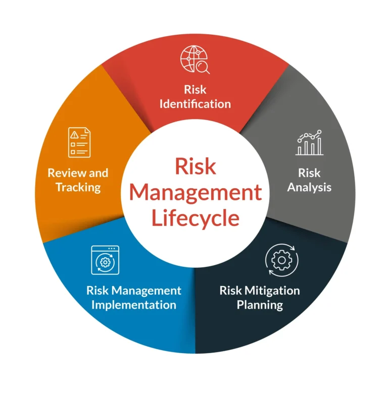
Identify: Systematically identify technical, programmatic, and external risks that could affect program outcomes. Use techniques including brainstorming, assumption analysis, SWOT analysis, and lessons learned from previous programs.
Assess: Evaluate identified risks for likelihood of occurrence and magnitude of impact. Use qualitative or quantitative methods appropriate to the program’s risk tolerance and visibility requirements.
Mitigate: Develop and implement strategies to reduce likelihood, reduce impact, or improve detection of risks. Mitigation strategies should be specific, actionable, and assigned to responsible parties.
Monitor: Track risk indicators and mitigation progress throughout the program. Update risk status as conditions change and close risks that have been adequately mitigated or that have materialized and been resolved.
Risk Register Integration
The risk register should be integrated with the SEP and maintained as a living document. Each entry should include risk description, likelihood assessment, impact assessment, risk score, mitigation strategy, mitigation owner, risk indicators, and status. The register should be reviewed regularly by program leadership and risks escalated or de-escalated based on current assessment.
Related: Risk Management in Systems Engineering | Technical Performance Measurement
11. Mistake #8 – Non-Compliance with Industry Standards
Industry standards such as ISO/IEC/IEEE 15288, INCOSE guidance, SAE GEIA standards, EIA/ANSI standards, and DoD SEP guidance provide proven frameworks for structuring systems engineering activities. Non-compliance with these standards creates multiple risks: program findings during audits, contractual non-conformance, and reduced confidence in engineering rigor. More fundamentally, standards codify lessons learned from decades of systems engineering practice—ignoring them means repeating avoidable mistakes.
Consequences of Ignoring Standards
Programs that deviate from standards without documented rationale may be required to justify their approach to customers or regulators. In some cases, non-compliance can lead to contract penalties or program termination. When quality assurance audits reveal non-conformances, addressing them requires additional effort that may not have been planned or budgeted.
Understanding Relevant Standards
ISO/IEC/IEEE 15288: Defines the system lifecycle processes that guide systems engineering from concept through disposal. Key processes include stakeholder needs and requirements definition, system requirements definition, architecture definition, design definition, system integration, verification, validation, operation, maintenance, and disposal.
INCOSE Systems Engineering Handbook: Provides practical guidance for applying systems engineering processes in real-world programs. It elaborates on ISO/IEC/IEEE 15288 with implementation guidance, tool recommendations, and examples. INCOSE also offers professional certifications including Certified Systems Engineering Professional (CSEP) and Expert Systems Engineering Professional (ESEP).
SAE ARP4754A: Provides guidelines for development of aircraft and aircraft systems, establishing certification considerations for aerospace programs.
ISO 26262: Addresses functional safety for automotive applications, providing requirements for safety lifecycle activities including hazard analysis and safety concept development.
ISO 21448 (SOTIF): Addresses safety of the intended functionality for autonomous driving systems.
MIL-STD-499/MIL-STD-499B: Military standards for systems engineering that provide requirements for defense acquisition programs.
Automotive SPICE: A framework for assessing software development processes in the automotive industry.
SAE GEIA Standards: Address specific domains such as electronic interoperability, logistics, and program management within the systems engineering context.
DoD SEP Guidance: For defense programs operating under DoDI 5000.02, provides specific requirements for SEP content, review timing, and approval authority coordination.
NASA Systems Engineering Manual: Provides guidance specific to NASA programs, including application of NPR 7123.1 requirements.
Compliance Checklist
The following table maps common SEP sections to relevant standards, providing a basis for compliance verification:
| SEP Section | ISO/IEC/IEEE 15288 Process | INCOSE Guidance Reference |
|---|---|---|
| Requirements Management | Stakeholder Requirements Definition, System Requirements Definition | Chapter 4 – Requirements Engineering |
| Architecture Definition | Architecture Definition | Chapter 5 – Architecture |
| Verification Planning | Verification | Chapter 7 – Verification |
| Risk Management | Risk Management (Technical Management Process) | Chapter 9 – Technical Management |
| Configuration Management | Configuration Management (Technical Management Process) | Chapter 9 – Technical Management |
| Stakeholder Engagement | Stakeholder Needs and Requirements Definition | Chapter 3 – Stakeholder Needs and Requirements |
Related: ISO/IEC/IEEE 15288 Implementation Guide | INCOSE Standards Overview
12. Mistake #9 – Weak Configuration Management
Configuration management ensures that the correct version of each configuration item is used throughout the program, that changes are evaluated and approved before implementation, and that the relationship between items is maintained and documented. Without effective configuration management, programs struggle to reproduce system states, understand change impacts, or demonstrate that delivered products match approved baselines.
Version Control Issues
When version control is inadequate, engineers may work from outdated baselines, unknowingly incorporate incompatible changes, or lose work when files become corrupted or overwritten. These issues consume time that could be spent productively and create confusion during integration and testing activities.
Baseline Creation
The Systems Engineering Plan should define the baselines that will be established during the program. Common baselines include:
- Functional Baseline: Approved stakeholder requirements and functional architecture.
- Allocated Baseline: Approved requirements allocated to configuration items, along with the functional and physical architecture.
- Product Baseline: Approved design documentation and related qualification evidence for configuration items.
Each baseline should be documented, reviewed, and approved through a formal process before subsequent design activities build upon it.
Change Control Boards
Changes to baselines should be processed through a change control board that evaluates change requests for impact on cost, schedule, and technical performance. The board should include representatives from engineering, program management, and affected stakeholder communities. The SEP should define board composition, authority levels, and processing timelines.
Configuration Audits
Configuration audits verify that the physical and functional characteristics of configuration items match their documentation. Functional configuration audits verify that the item’s design documentation accurately describes the item’s functional characteristics. Physical configuration audits verify that the delivered item matches its design documentation. The SEP should schedule these audits and ensure that audit findings are resolved before program completion.